


Figure 3 - MPLS Device Roles [_/su_spoiler]
Figure 1 - MPLS Ethernet Frame [_/su_spoiler]
[__/su_spoiler]
[__/su_spoiler] [_/su_spoiler]
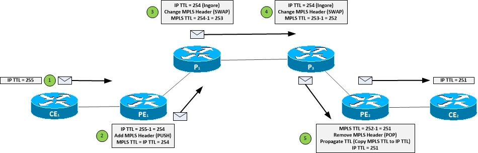
Figure 2 - MPLS TTL [_/su_spoiler]
Only Transport session uses authentication through TCP session Configured on a per neighbor basis Command mpls ldp neighbor <peer ip> password <password> Requires a restart to the neighbor adjacency clear mpls ldp neighbor * If not password set for a specific neighbor can use a global fallback password for neighbors that require is mpls ldp password fallback <password> Can force LDP neighbors to establish authenticated adjacency Local device will not bring up any unauthenticated adjacencies mpls ldp password required show mpls ldp neighbor <peer> detail To change router id on MPLS router mpls ldp router-id <interface> force [___/su_spoiler]
[___/su_spoiler]
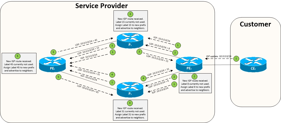
Figure 4 - MPLS Label Distribution Process [___/su_spoiler]
[___/su_spoiler]
[___/su_spoiler]
[___/su_spoiler] [__/su_spoiler] [_/su_spoiler]
[__/su_spoiler]
[__/su_spoiler] [_/su_spoiler]
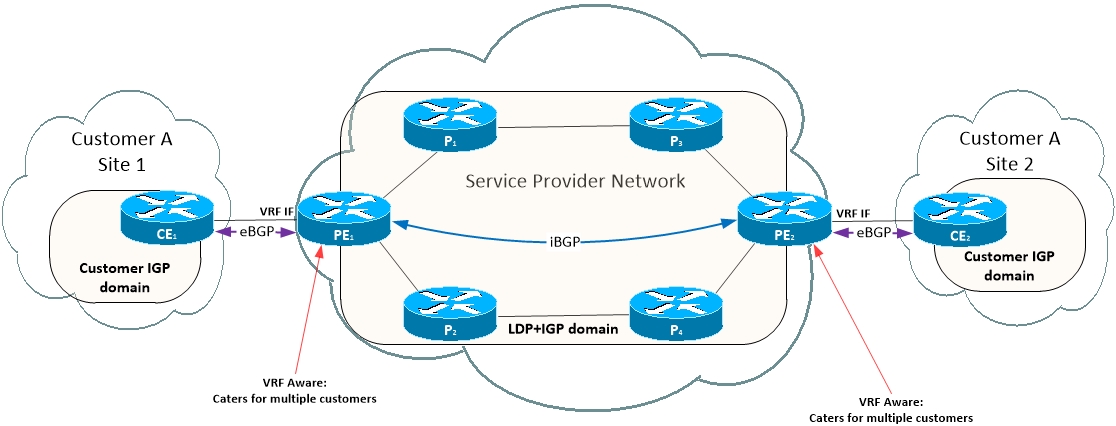
Figure 5 - MPLS Protocol Boundaries
[__/su_spoiler]
Figure 6 - Route Distinguisher (RD) and Route Target (RT) [__/su_spoiler]
Figure 7 - MPLS Transport and VPN Label Header [__/su_spoiler]
[__/su_spoiler]
[__/su_spoiler] [_/su_spoiler]
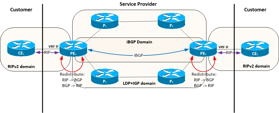
Figure 8 - CE to PE routing with RIPv2 [_/su_spoiler]
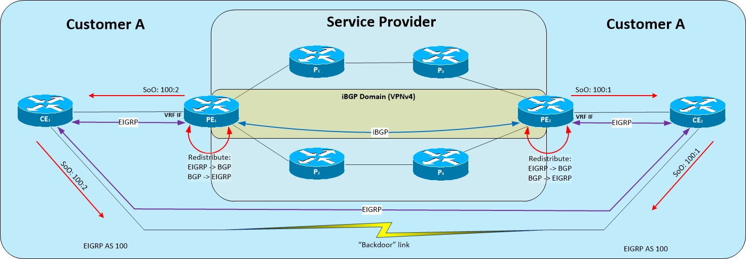
Figure 9 - CE to PE routing with EIGRP
Figure 10 - MPLS EIGRP Site of Origin [__/su_spoiler] [_/su_spoiler]
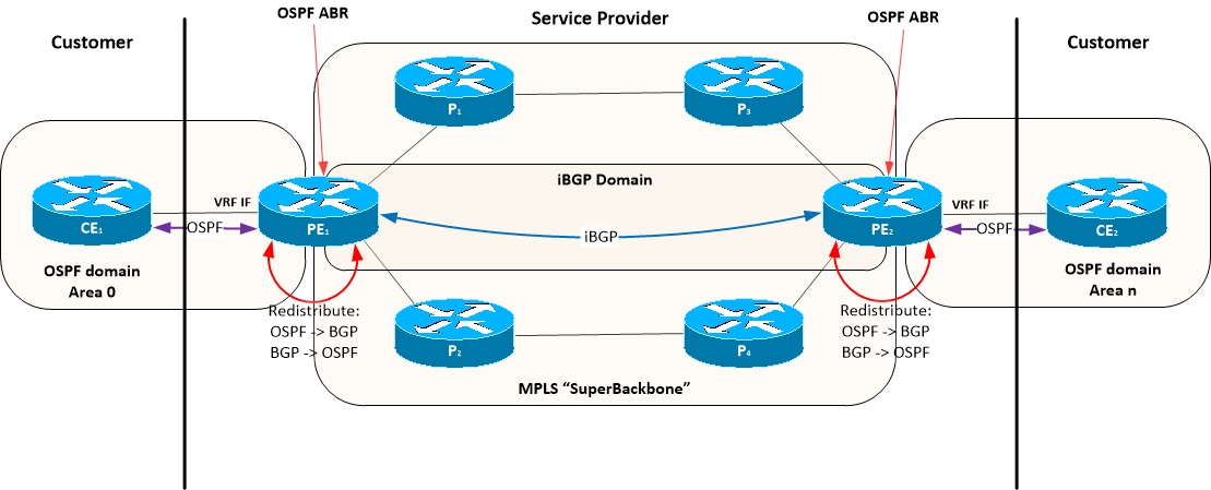
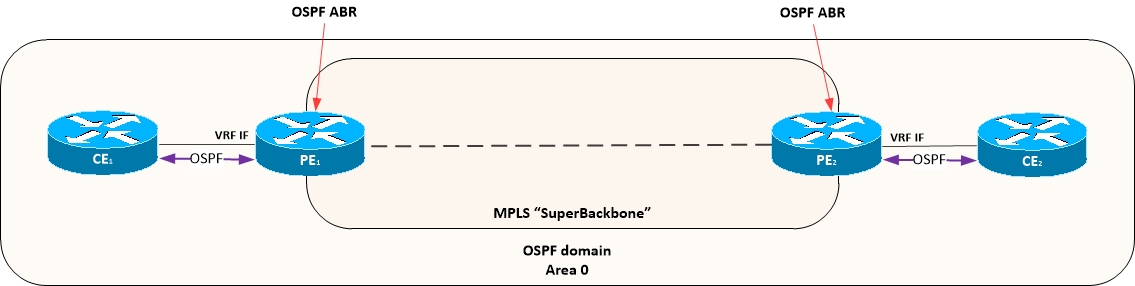
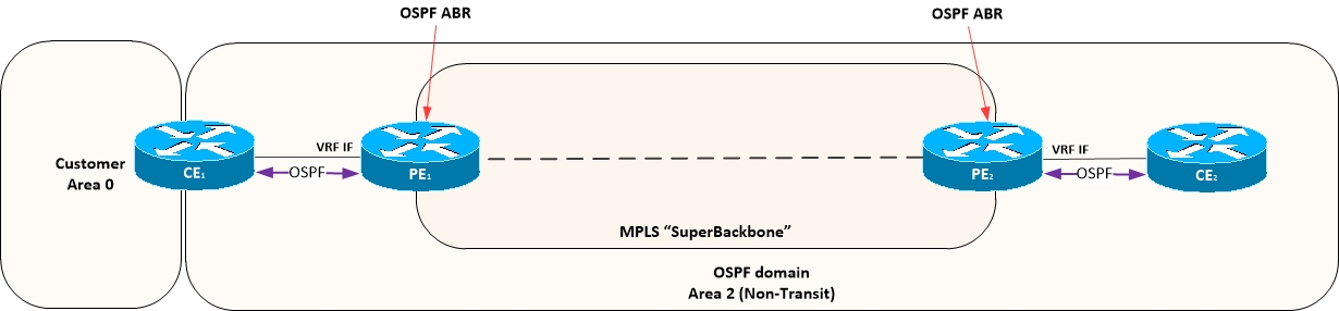
Figure 10 - CE to PE routing with OSPF
Figure 11 - PE routing Design with OSPF Option 1 Figure 12 - PE routing Design with OSPF Option 2 Figure 13 - PE routing Design with OSPF Option 3 [__/su_spoiler]
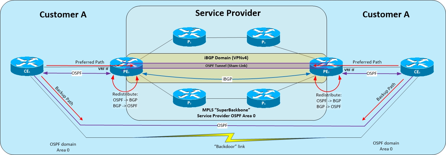
Figure 14 - MPLS OSPF Sham-Link [__/su_spoiler] [_/su_spoiler]
[__/su_spoiler]
[__/su_spoiler] [_/su_spoiler]
MPLS Overview Summary
Function/Feature
Description
Protocol Type
Distance Vector Label Switching
RFC / Proprietary
RFC3306
Best path selection
Relies on IGP to calculate best path
Transport protocol
UDP/646 for Phase 1TCP 646 for Phase 2
Label Distribution Hello interval
Update destination
Update interval
Full of partial updates
Triggered updates
Authentication
MPLS Device Roles
Device Role
Device Abbreviation
Description
Customer Edge Device
CE
Doesn't know about MPLS
Runs normal routing processes and protocols
Last hop in customer network before connecting to carrier
Provider Edge Device
PE
Label Edge Router
Last hop in carrier network before connecting to customer
Performs routing to the customer and label switching internally to the carrier network
Performs Label imposition / deposition
VRF Aware
Requires end to end connectivity between PEs (Label Switched Path)
PE to PE need to peer (MP-BGP) on Loopback addresses
Creates Label Switching Paths towards carrier network
Provider Device
P
Label Switching RouterCore devices in carriers network
Performs label Swap function
Switches packets based on MPLS labels
Creates Label Switched Paths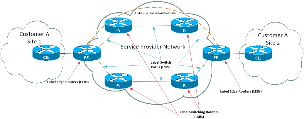
MPLS Packet Format

Length (bits)
Field
Details
20
Label value
Identifies label number attached to packet
3
EXP (Experimental)
QoS (CoS) marking field
1
S (Bottom-of-Stack)
When packets hold multiple MPLS headers, this bit indicates if this is the last label in the stack assigned to a packet
8
TTL (Time-to-Live)
Used for same purpose as IPv4 TTL value
Label Information Base (LIB)
Label Forwarding Information Base (LFIB)
MPLS TTL
MPLS Label Distribution
Label Distribution Protocol
LDP Messages
LDP Addresses
LDP Label Distribution Process
LDP Label Filtering
LDP Configuration
Virtual Routing and Forwarding (VRF)
VRF Configuration
VRF Troubleshooting
MPLS Layer 3 VPNs
Route Distinguisher (RD)
Route Target (RT)

Transport and VPN Label

Multiprotocol BGP (MP-BGP)
IPv6 over MPLS
MPLS CE to PE RIPv2 Routing
MPLS CE to PE EIGRP Routing

EIGRP Site of Origin
MPLS CE to PE OSPF Routing
MPLS OSPF PE Routing Design Options
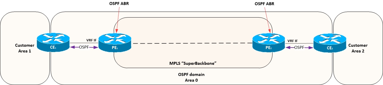
OSPF Sham Links
MPLS CE to PE BGP Routing
BGP Site of Origin
BGP Multipath
