STP Overview Summary
Spanning-Tree Protocol Overview Summary
- Provides a loop-free Layer 2 topology
- Uses the concept of a Root Bridge
- All Layer 2 traffic is forwarded towards the Root Bridge
| |
Name |
Standard |
Resources |
Convergence Time |
VLANs |
| CST |
Common Spanning Tree |
802.1d |
Low |
Slow |
All VLANs |
| PVST+ |
Per-VLAN Spanning Tree |
Cisco |
High |
Slow |
Per VLAN |
| RSTP |
Rapid Spanning Tree |
802.1w |
Medium |
Fast |
All VLANs |
| PVRST+ |
Per-VLAN Rapid Spanning Tree |
Cisco |
Very High |
Fast |
Per VLAN |
| MSTP |
Multiple Spanning Tree |
802.1s |
Medium or High |
Fast |
VLAN List |
STP Topology
STP Topology
- Process to build the STP topology:
- Elect a Root Bridge
- Elect Non-Root Bridges Root ports
- Elect Designated ports
Bridge Protocol Data Units (BPDUs)
Bridge Protocol Data Units
- 2 types of BPDUs
- Configuration BPDU
- Topology Change Notification (TCN) BPDU
- Both types sent in STP Hello BPDUs
| Configuration BPDUs |
Topology Change Notification BPDUs |
| Field |
Length(Bytes) |
Value |
Field |
Length(Bytes) |
Value |
| Protocol Identifier |
2 |
0x0000 |
Protocol Identifier |
2 |
0x0000 |
| Protocol Version |
1 |
0x00 |
Protocol Version |
1 |
0x00 |
| BPDU Type |
1 |
0x00 |
BPDU Type |
1 |
0x80 |
| Flags |
1 |
Indicates message information |
| Root Bridge ID |
8 |
RBID |
| Root Path Cost |
4 |
RPC |
| Sending Bridge ID |
8 |
SBID |
| Sending port ID |
2 |
SPID |
| Message Age |
2 |
Age since originated from RB |
| Max Age |
2 |
When current configuration
message should be deleted |
| Hello Time |
2 |
Time between Hello's |
| Forward Delay |
2 |
Time to wait before transitioning
to a new state after topology change |
- Further field information:
- Version ID:
- 0x00 Config & TCN
- 0x02 RST
- 0x03 MSTP
- 0x04 SPT
- BPDU Type:
- 0x00 Config BPDU
- 0x80 TCN BPDU
- 0x02 RST BPDU
- Flags:
- 1 :
- 2 :
- 3-4 :
- 01 = Alternate/Backup Port Role
- 10 = Root Port Role
- 11 = Designated Port Role
- 5 :
- 6 :
- 7 :
- 8 :
- 1 = Topology Change Acknowledgement
- Sending Bridge ID:
- CIST Regional Root ID in MST/SPT BPDU
- Message Age:
- Max Age:
- Hello Time:
- Forward Delay:
[_/su_spoiler]
Bridge ID
Original 802.1d format Bridge ID
| Priority |
System ID |
| (0 - 65535) |
MAC Address |
| 2 Bytes |
6 Bytes |
Current Format with System Extension Bridge ID
| Priority |
System ID Extension |
System ID |
| Multiple of 4096 |
Contains VLAN 1-4096 |
MAC Address |
| 4 bits |
12 bits |
6 Bytes |
- Bridge ID consists of:
- Bridge Priority
- Value of 0 - 61440
- Set in increments of 4096
- Default is 32768
- Lower value is preferred
- 4 bits
- System ID Extension
- Value of 0 - 4095
- VLAN ID
- 12 Bits
- MAC Address
- Bridge ID (BID) can be set manually
- With specific priority value
- Command:
- (config)#spanning-tree vlan <vlan> priority <1 - 61440>
- Using root bridge macro
- Command:
- (config)#spanning-tree vlan <vlan> root [primary | secondary]
- Sets the priority number based on the current Root Bridge priority
- 4096 lower than current Root Bridge
[_/su_spoiler]
STP Root Bridge
- Used as a reference point for other Non-Root Bridges to determine path
- Only a single Root Bridge is elected in Layer 2 network
- Only the Root Bridge Generates BPDUs
- All other bridges forward them on
- Root Bridge sets timers
- All other bridges use these timer settings
- Can set manually on NON-Root bridges but unless that switch becomes the Root Bridge, the timers are ignored
- Timers include:
- Hello timer
- Fordwarding Delay timer
- Max_Age timer
Root Bridge Election
- All switches begin by sending STP Hello BPDUs claiming to be the Root Bridge
- If a switch receives a superior Hello BPDU (Lower BID), it stops claiming to be the Root Bridge by stopping originating Hello BPDUs
- Switch starts forwarding the superior Hello BPDUs received
- Eventually all switches stop forwarding Hello BPDUs except the Root Bridge's Hello BPUs
- Switch with lowest Bridge ID in the network becomes the Root Bridge.
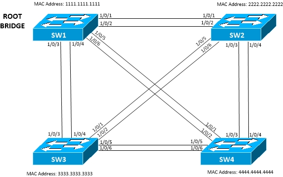
Figure 1 - STP Bridge Election
- In the above diagram, all priorities being equal, SW1 will become the Root Bridge as it has the lowest MAC address,
- Therefore the lowest Bridge ID
[_/su_spoiler]
Root Port Election
- Once Root Bridge elected, the following happens:
- All Non-Root Bridges elect a Root Port
- All Non-Root Bridges elect their Designated Ports
- All Non-Root Bridges put all other ports as Alternate Ports
- Each Non-Root Bridge adds the local port cost to the Root Path Cost (RPC) of received BPDUs
- Lowest or superior RPC is now set to Root Port
- Hellos received on Root Port are forwarded through Designated Ports
- Updates RPC, Sender Bridge ID, Sender Port ID and MessageAge
- Hellos received on other ports of Non-Root Bridge are processed but not forwarded
- Do not forward Hellos out Root Ports or blocking ports
- Selection:
- Prefer neighbor advertising lowest cost to root (RPC)
- Equal cost tie breakers:
- Prefer neighbor with lowest Bridge ID (BID)
- Prefer the lowest Sender Port ID (SPID)
- Default value is 128 + port number
- 1st port will be 128.1
- 20th port will be 128.20 etc
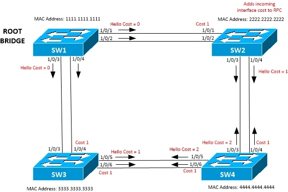
Figure 2 - Root Bridge Cost Advertisement
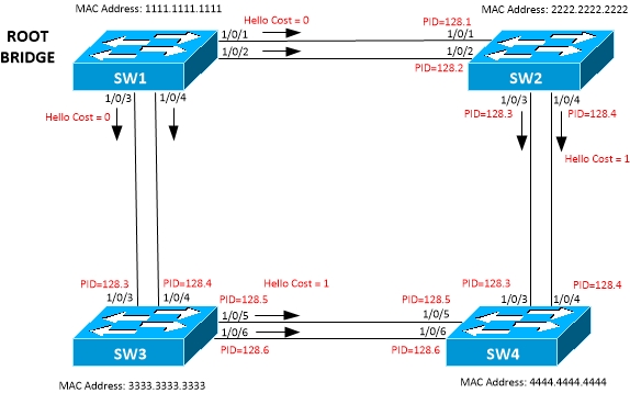
Figure 3 - Port Priority used for tie-breaker
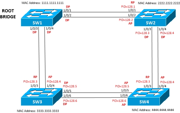
Figure 4 - Port Role allocation

Figure 5 - Port Role Allocation in 3 Switch Topology
[_/su_spoiler]
Designated Port Election
- Only the Designated Port forwards Hellos on to a segment
- On the Root Bridge, all ports are Designated Ports
- Designated Ports face away from the Root Bridge
- To become a Designated Port a switch must send superior BPDUs on a LAN segment
- Uses same selection process as Root Port election:
- Prefer neighbor advertising lowest cost to root (RPC)
- Equal cost tie breakers:
- Prefer neighbor with lowest Bridge ID (BID)
- Prefer the lowest Sender Port ID (SPID)
- Refer to Figure 4 and 5 for Port Role allocation on topology example
[_/su_spoiler]
STP Timers
Spanning Tree Timers
- 3 main timers are used by Spanning Tree
- Hello timer
- Default is 2 seconds
- Time between each BPDU sent on port
- Originated by Root Bridge
- Sent out all DP
- Received on all RP
- Can be configured manually on Root Bridge only
- Command:
- (config)#spanning-tree vlan <vlan-id> hello-time <1-10 seconds>
- Forward Delay timer
- Default of 15 seconds
- Time to spend in Listening and Learning port states
- Can be configured manually on Root Bridge only
- Command:
- (config)#spanning-tree vlan <vlan-id> forward-time <4-30 seconds>
- Max Age timer
- Default of 20 seconds
- Length of time to wait before initiating a topology change if stops receiving Hllo BPDUs
- Can be configured manually on Root Bridge only
- Command:
- (config)#spanning-tree vlan <vlan-id> max-age <6-40>
STP Topology Change
Spanning Tree Topology Change
- Happens when:
- Receives Topology Change Notification (TCN) BPDU on DP
- Port moves from Learning or Forwarding to Blocking
- A switch becomes the Root Bridge
- Port moves to Forwarding and has at least 1 DP
- When Topology Change happens, the CAM table needs to be flushed due to invalid entries
- All switches notified to flush CAM
- Each switch uses a short timer equivalent to Forward Delay to time out CAM table entries
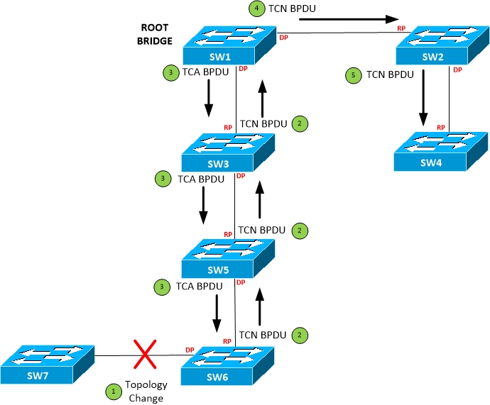
Figure 6 – STP Topology Change Process
- Topology change event
- Each switch generates a TCN BPDU sent out its Root Port towards the Root Bridge for every Hello time until receives acknowledgement.
- Once received TCN BPDU, each switch sends back an acknowledgement through its next forwarded BPDU by setting the TCA bit in the flags field
- Once TCN reaches Root Bridge, RB floods throughout network with TC bit set, for MaxAge + Forward Delay. Informs other switches to reduce CAM age time to Forward Delay value
STP Path Cost
Spanning Tree Path Cost
- STP Path Cost is accumulated based on bandwidth
- The higher the bandwidth of a link, the lower the cost
- The cost is all relative to the Root Bridge
Default Costs
|
802.1D-1998 |
802.1D-2004 |
| Port Speed |
CST/RSTP |
MSTP |
| 10Mbps |
100 |
2000000 |
| 100Mbps |
19 |
200000 |
| 1Gbps |
4 |
20000 |
| 10Gbps |
2 |
2000 |
- 802.1d-2004 costs can be enabled manually for RSTP or PVST
- Command:
- (config)#spanning-tree pathcost method long
- Default command is:
- (config)#spanning-tree pathcost method short
STP Modes
STP Mode: Common Spanning Tree (CST)
Common Spanning Tree
- Original STP specification
- 802.1D standard
- Legacy protocol
- Not recommended for use
- All VLANs under single instance
- Flags field only uses 2 out of the 8 bits
- Bit 1: Topology Change
- Bit 8: Topology Change Acknowledgement
CST Port Roles
- Root Port
- Forwarding state
- Only on Non-Root Bridges
- Only single port towards Root Bridge
- Forwards traffic to Root Bridge
- Designated Port
- Forwarding state
- On Root and Non-Root Bridges
- Ports facing away from Root Bridge
- Receives traffic going towards Root
- On Root Bridge all ports are Designated
- Non-Designated Port
- Blocking state
- Only on Non-Root Bridges
- Receives BPDUs
- Discards all other traffic
- Unable to send traffic
- Disabled
- Shutdown port
- Doesn't participate in STP

Figure 7 - Port Role allocation with CST
-
- As all priorities are equal and MAC addresses will be the same for both links, the selection is made on Port priority which is 128 plus the port number.
- To manually change a Port Role:
- Modify the cost of the port on an interface
- This changes the default cost added to BPDUs Root Path Cost in the inbound direction
- Command:
- (config-if)#spanning-tree vlan <vlan> cost
- (config-if)#bandwidth <kbps>
- Modify the Port ID
- If the costs are equal, this will advertise a different port priority to neighbor.
- Command:
- (config-if)#spanning-tree vlan <vlan> port-priority <port-priority>
- <port-priority> must be in increments of 64 (0-192)
[__/su_spoiler]
CST Port States
- Blocking
- Receives BPDUs to determine location of Root Bridge
- Would cause a loop if active
- Time in state set by MaxAge timer
- Listening
- Receives and transmits BPDUs
- Doesn't populate MAC table
- Doesn't forward frames
- Time in state set by Forward Delay timer
- Learning
- Prepares to participate in forwarding
- Doesn't forward frames
- Populates CAM table
- Time in state set by Forward Delay time
- Forwarding
- Considered part of the active topology
- Populates CAM table
- Sends and receives BPDUs
- Forwards frames
- Disabled
- Doesn't participate in STP
- Doesn't forward frames
[__/su_spoiler]
[_/su_spoiler]
Rapid Spanning-Tree (RSTP)
- 802.1W standard
- Single STP instance covering all VLAN
- Automatically backwards compatible with CST
- Shown by "P2P Peer (STP)" on Link Type
- Will revert to legacy protocol process on this interface
- Command:
- (config)#spanning-tree mode rapid-pvst
- Flags field
- Doesn't use TCA bit
- Uses a Proposal/Agreement process
- Each switch originates its own BPDUs
- Contents based on Root Switch BPDU
RSTP Root Port Election
- Uses a Proposal/Agreement and Synchronisation operation
- When electing a Root port, assume all other Non-Edge ports are Designated
- Non-Edge ports are Discarding
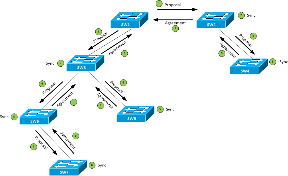
Figure 8 - RSTP Proposal/Agreement and Sync process
- Sends proposal out all Designated ports
- Proposal has Port role set to Designated
- Contains Root Bridge information
- Set to Discarding state
- Downstream switch reviews and synchronises information
- If they don't have a better path to the Root Bridge, they agree
- Elects a local Root Port
- Blocks all non-edge Designated ports
- Starts sync process on all Designated ports (Step 4)
- If they have a better path, they announce their information
- Local switch changes Root Port
- Downstream switch sends agreement to upstream switch
- When Designated port receives agreement
- Port is unblocked
- Moved straight to Forwarding state
- Proposal sent to next downstream switch
- Downstream switch reviews and synchronises information
- Downstream switch sends agreement to upstream switch
- Process continues.....
[__/su_spoiler]
RSTP Port Roles
- Root Port
- Does not use link-type parameter
- Same role as 802.1d
- Forwarding state
- Alternate
- Does not use link type parameter in most cases
- Equivalent of Uplinkfast
- Fast Root path recovery
- Replacement for Root Port
- Discarding state
- Designated
- Uses link type parameter
- Rapid transition to forwarding only occurs if link type P2P
- Same role as 802.1d
- Forwarding state
- Backup
- Replacement for Designated port
- Activated if primary Designated Port fails
- Discarding state
- Not quick transition, driven by timers
- Edge port
- Equivalent of Portfast
- Straight to forwarding state
- Doesn't generate TCN if changes state
[__/su_spoiler]
RSTP Port States
- Discarding
- Outbound BPDUs have Proposal bit set
- Default state when newly activated (unless Edge port)
- Doesn't forward or receive frames
- Processes BPDUs
- Send and receives inter-switch signalling protocols such as LACP, DT< CDP, VTP, etc
- Learning
- Outbound BPDUs have Proposal bit set
- Same functionality as 802.1d Learning state
- Forwarding
- Same functionality as 802.1d Forwarding state
- Forwards frames
- Ports are put into Designated Blocking state until they receive BPDU from counterpart
[__/su_spoiler]
RSTP Link Types
- Edge Ports
- immediately transitions to Designated Forwarding state
- Similar to PortFast
- Never have a switch connection
- When receives a BPDU
- Looses Edge port status and becomes Non-Edge STP port
- Generates a TCN
- Non-Edge Ports
- Default port type on Cisco switches
- Point-to-Point
- Full Duplex
- Single RSTP switch connection
- Shared
- Half Duplex
- Multiple RSTP switch connections
- Link-type must be accurate
- Can be configured manually
- Command:
- (config-if)#spanning-tree link-type <point-to-point | shared>
- (config-if)#spanning-tree portfast [trunk]
[__/su_spoiler]
RSTP Timers
- Hello timer
- Each bridge generates own BPDUs
- Every 2 seconds by default
- If 3 hellos missed from neighbor, reconvergence begins
- Information on port is aged out
- 6 seconds vs. 20 seconds MaxAge
- MaxAge used as hop count
- Every bridge sends BPDUs on own
- If BPDU MessageAge is equal to or higher than MaxAge, it is discarded
- MaxAge also used on Shared ports for legacy CST backwards compatibility
- Faults detected faster based on physical layer signalling
[__/su_spoiler]
RSTP Re-convergence
- Needs to re-converge if Root port is lost
- If there is an Alternate port, it is selected in its place
- New Root port then synchronised with downstream bridges
- Same functionality as Uplinkfast
- If there is no Alternate port and no better information available
- Declare local bridge as Root bridge
- Synchronise decision
- Adapt to better information
- Keep topology as small as possible
- RSTP suffers from count-to-infinity depending on scale of design
[__/su_spoiler]
[_/su_spoiler]
Multiple Spanning-Tree
- 802.1S standard
- Convergence a lot quicker than PVST+
- Backward compatible with
- 802.1D (CST)
- 802.1W (RSTP)
- Inherits all RSTP functionality
- If doesn't hear response from other bridges in MST, falls back to legacy protocol
- Displayed as port type P2P Bound (STP)
- CIST (Common and Internal Spanning Tree) Root must be within MST domain
- Behaves like inter-region MST
- Maps multiple VLANs to a single Spanning Tree instance
- As opposed to 1 instance per VLAN (RSTP) or 1 instance for all VLANs (CST)
- provides better scalability
- Decouples VLAN and STP instance
- Enables load balancing across multiple paths
MSTP Bridge ID
- Consists of:
- Bridge Priority
- 4 bits
- Increments of 4096
- Extended System ID
- 12 bits
- Carries MST instance number instead of VLAN number
- MAC Address
[__/su_spoiler]
MSTP Regions

Figure 9 - MST Regions
- Each switch has a single MST Region configuration
- All bridges must agree on configuration
- Region Configuration consists of:
- Name
- Revision Number
- VLAN Association table
- VLAN to STP instance mappings
- Instance 0 used for CIST (Common Internal Spanning Tree) which is used for Inter-region root bridge election
- This must be configured manually on each switch
- VTPv3 supports MST including mappings
- VLAN to instance mapping not propagated in BPDUs
- If 2 switches differ on 1 or more attributes, they are part of 2 different regions
- BPDUs contain only a digest of VLAN to instance mapping, revision number and name
[__/su_spoiler]
MSTP Intra vs. Inter Region
Intra Region vs Inter Region
- Intra region
- Details known within MST Region
- VLAN to STP instances are manually defined
- Undefined VLANs fall into CIST (MST 0)
- Inter Region
- Details between MST Regions are not known
- Different regions see each other as Virtual Bridges (Figure 11)
- Simplified Inter-Region calculation
- Seen as a single switch
- Intra-region MSTs are collapsed into CIST
- A Regional Root Bridge is elected internally per Region
- CIST Root bridge is elected for all Regions (Figure 10)
- Unlikely to see in a real design as scalability/hardware issues
- Too many MAC addresses on network
- Not enough TCAM memory etc.
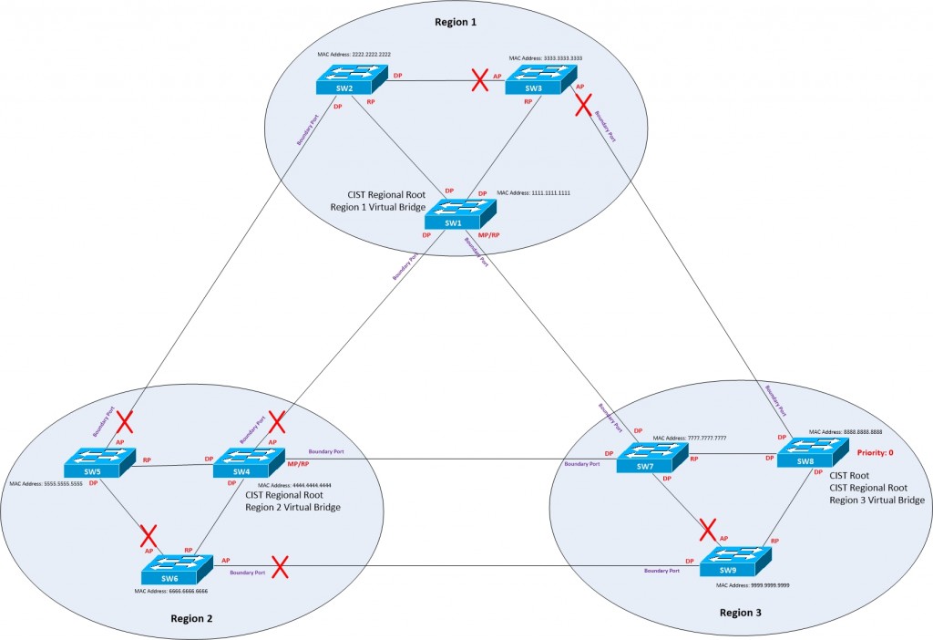
Figure 10 - Multiple Regions

Figure 11 - MST CIST 0 Virtual Bridges
[__/su_spoiler]
MSTP Configuration
- Real configuration would need to start on Root Bridge and work out
- Set the Spanning-Tree mode
- Command:
- (config)#spanning-tree mode mst
- Enable MST globally
- Command:
- (config)#spanning-tree mst configuration
- Define Region Name
- Command:
- (config-mst)#name <instance name>
- Define Revision Number
- Command:
- (config-mst)#revision number <1 - 65535>
- Define VLAN to instance mappings
- Command:
- (config-mst)#instance <instance> vlan <vlan IDs>
- To change the Root Bridge manually
- Command:
- (config)#spanning-tree mst <instance> priority <priority>
- To change Port cost manually
- Command:
- spanning-tree mst <instance> cost <cost>
- To change Port ID manually
- Command:
- (config)#spanning-tree mst <instance> port-priority <priority>
[__/su_spoiler]
[_/su_spoiler]
Cisco STP Toolkit
Cisco STP Toolkit
Portfast
- Configures interface type as Edge ports
- Transitions directly to forwarding state
- Effects TCN generation
- Spanning Tree not enabled on these ports
- Configured in Global mode:
- Enables on all ports unless BPDUs received
- Transitions to normal STP port
- Command:
- (config)#spanning-tree portfast default
- Configured in Interface mode
- Command:
- (config-if)#spanning-tree portfast
- (config-if)#spanning-tree portfast trunk
[_/su_spoiler]
UplinkFast
- Provides 3 to 5 seconds of convergence after a Root port link failure if alternate port available
- Could potentislly change topology as other switches may avoid uplinkfast switch as metric set high
- Not required with PVRST+ or Rapid Spanning Tree
- Command:
- (config)#spanning-tree uplinkfast
[_/su_spoiler]
BackboneFast
- Cuts convergence time by MAX_AGE for an indirect failure
- When receives inferrior BPDU
- Needs to be enabled everywhere
- Not required with PVRST+
- Command:
- (config)#spanning-tree backbonefast
[_/su_spoiler]
BPDU Guard
- Shuts down port if BPDU received
- Configured in Global mode
- Command:
- (config)#spanning-tree portfast bpduguard default
- Configured in Interface mode
- Command:
- (config-if)#spanning-tree bpduguard enable
[_/su_spoiler]
BPDU Filter
- Configured in Global mode
- Any Portfast port receiving BPDU becomes a standard port
- Command
- (config)#spanning-tree portfast bpduguard default
- Configured in Interface mode
- Ignores BPDUs and doesn't send any
- Command:
- (config-if)#spanning-tree bpdufilter enable
[_/su_spoiler]
RootGuard
- If receives superior BPDU than current Root Bridge, port is moved to a Root-Inconsistent state (STP Listening)
- Can not be used at the same time as LoopGuard
- LoopGuard does opposite of RootGuard
- Configure on downstream Designated ports
- Command:
- (config-if)#spanning-tree guard root
[_/su_spoiler]
Loop Guard
- Similar to UDLD
- If link isn't receiving BPDUs, moves to a Loop-Inconsistent state (STP Blocking)
- When receives BPDU, transitions normally
- Only monitors Non-Designated ports and prevents them from becoming Designated
- Used on unidirectional links
- Can not be used at the same time as RootGuard
- RootGuard does opposite of LoopGuard
- Configured in Global mode:
- Command:
- (config)#spanning-tree loopguard default
- Configured in Interface mode:
- Command:
- (config-if)#spanning-tree guard loop
[_/su_spoiler]
STP UDLD
UniDirectional Link Detection
- Cisco proprietary feature
- UDLD detects when a link is unidirectional and shuts down the affected interface
- Layer 2 protocol that works with Layer 1 mechanisms
- Periodically transmits UDLD packets on enabled interface
- If packets are not echo’d back, link is considered unidirectional
- Devices both ends must support UDLD
- UDLD uses well-known MAC address 0100.0CCC.CCCC to send frames
- Each switch sends its own Device ID, Originator Port ID and timeout value to neighbor
- Remote peer echos back ID of neighbor
- If no frame received with device’s own ID for a certain amount of time, port considered unidirectional
- Modes:
- Normal
- If stops receiving UDLD message but physical port is up, changes port state to Undetermined.
- Doesn’t disable the port
- More informational
- Doesn’t prevent physical loops
- Aggressive
- Sends frames 8 times ievery seconds to attempt to re-establish UDLD
- If no response port considered Unidirectional
- Put in err-disable state
- Not automatically recovered unless err-disable recovery is configured
- Preferred method of UDLD
- Subnetwork Access Protocol (SNAP)
- High Level Data-Link Control (HDLC) protocol type 0x0111
- Globally disabled by default
- Per-interface Fiber enabled by default
- Per-interface Copper disabled by default
Flex-Links
FlexLinks in access layer
- Layer 2 availability feature
- Can coexist with STP
- Enhancement allows convergence time of less than 50 milliseconds
- Active/Standby link pair is defined on a common access switch
- Interface can belong to only one flexlink
- Different interface types are allowed
- Loops are not detected due to no STP
- Failover is 1 to 2 seconds
- Supported on 4500 and 6500 series switches
- Supported on Layer 2 ports and port channels
- Not supported on VLAN interface or L3 ports
STP Troubleshooting Commands
Troubleshooting Commands
#show spanning-tree vlan <vlan>
#show spanning-tree root – Displays Root Bridge
#show spanning-tree detail – Shows end-to-end costs
#show spanning-tree interface detail – Shows detailed interface information on spanning tree


